Feature recognition in practice: solving real problems, not academic exercises
Discover how MTK recognizes real-world manufacturing features in CAD models — from partial holes to NURBS-based geometry. Built for engineers and developers, not theory.

When we talk about feature recognition (FR), it’s easy to assume it’s a solved problem. Recognize a hole, classify a pocket — sounds straightforward, right?
But real-life CAD models, especially those coming from external systems or STEP files, are messy. There’s no design history, no semantic tags like “this is a hole,” and no guarantee that a cylinder is actually even modeled as a cylinder. That’s the world where our MTK (Manufacturing Toolkit) operates every day — and where robust FR becomes a real engineering challenge.
Why feature recognition is still hard
Most models we see at MTK come as dumb B-Rep: raw boundary representation without construction history, parametric info, or metadata. Here’s what that means:
-
No design intent There’s no feature tree. You don’t know what was meant to be a hole or a boss — you just see faces, edges, and vertices.
-
CAD export ≠ CAD import Exporting from one CAD system and importing into another often leads to subtle (or not-so-subtle) issues:
- Cylinders become approximated as NURBS.
- Arcs get broken into small spline segments.
- Tolerances shift, faces don’t stitch perfectly.
-
Loss of analytic geometry What was once a clean analytic surface — like a cylinder (e.g. a hole) or torus (a fillet)— becomes a general-purpose spline surface. It still looks like a cylinder, but behaves like a NURBS. That’s why MTK includes a dedicated Analytic Recognition module that attempts to recover original geometry.
What real models look like
Let’s walk through a few examples — all based on real models from MTK users and clients.
1. Partial holes
Not every hole is a perfect cylinder with two caps. Sometimes the bottom face is missing, or the hole is open on one side. But for manufacturing, it’s still a valid through-hole.

2. Unclosed revolved surfaces
Some CAD tools like CATIA (or rather their underlying modeling kernels) often limit revolved surfaces to ≤180 degrees. As a result, you get trimmed or partial shapes that still represent meaningful features — like pockets or bosses — but require careful reconstruction.
")
3. NURBS instead of analytic geometry
We can see cylinders, cones or tori represented as complex NURBS surfaces, or arcs as NURBS curves. This may happen, for example, in the sending CAD system’s math kernel while processing original geometries with Boolean intersections or fillets, when approximation gets involved to close some gaps. These are visually identical but harder to classify. MTK handles these by applying heuristics to detect and reclassify them as their analytic counterparts.

4. Pockets and bosses
These features are often ambiguous:
-
Irregular side profiles
-
Varying depths
-
Blends and fillets obscuring boundaries → Simple rule-based classification doesn’t work here. MTK combines topology traversal and local surface analysis.

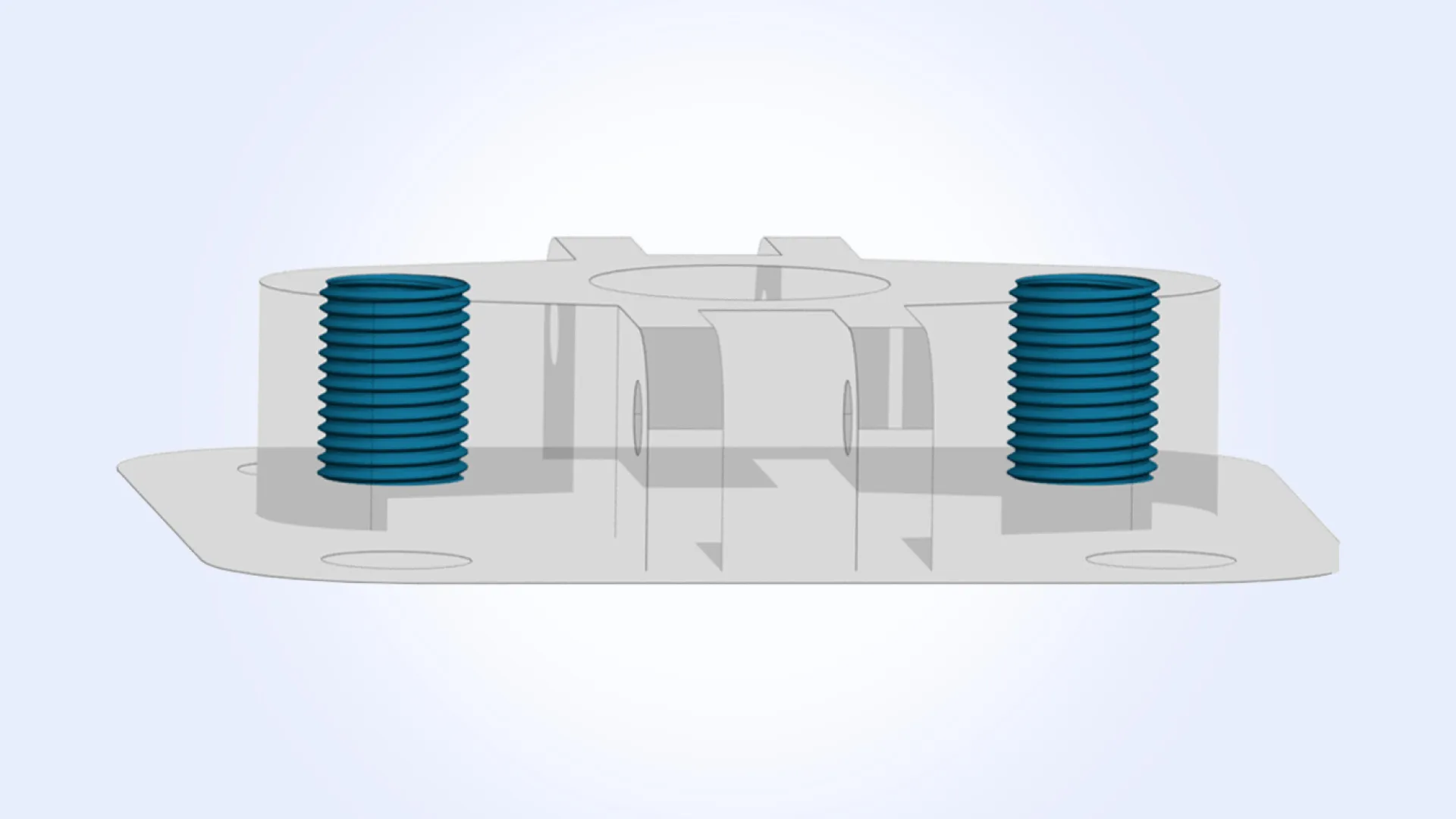
5. Threaded holes with geometry
Threads in holes may or may not be modeled in 3D. Sometimes it is meta-information attached in the CAD system as PMI. This can be exported as STEP PMI at best, or lost in transit keeping just naked geometry (often). Sometimes threads are modeled with actual thread geometry (typically NURBS). MTK checks for patterns — cylindrical bore + conical lead-in + thread body — and flags it appropriately.
NURBS definition is just a set of abstract mathematical values, having nothing to do with manufacturing or even holes. Imagine what it takes to decipher radius, step, pitch from the soup of these abstract values. A bachelor degree in math is a prequisite.
What it looks like in code
Here’s a simplified example from MTK’s CNC recognition pipeline (actual code is more complex and optimized):
Example 1: Recognizing a pocket
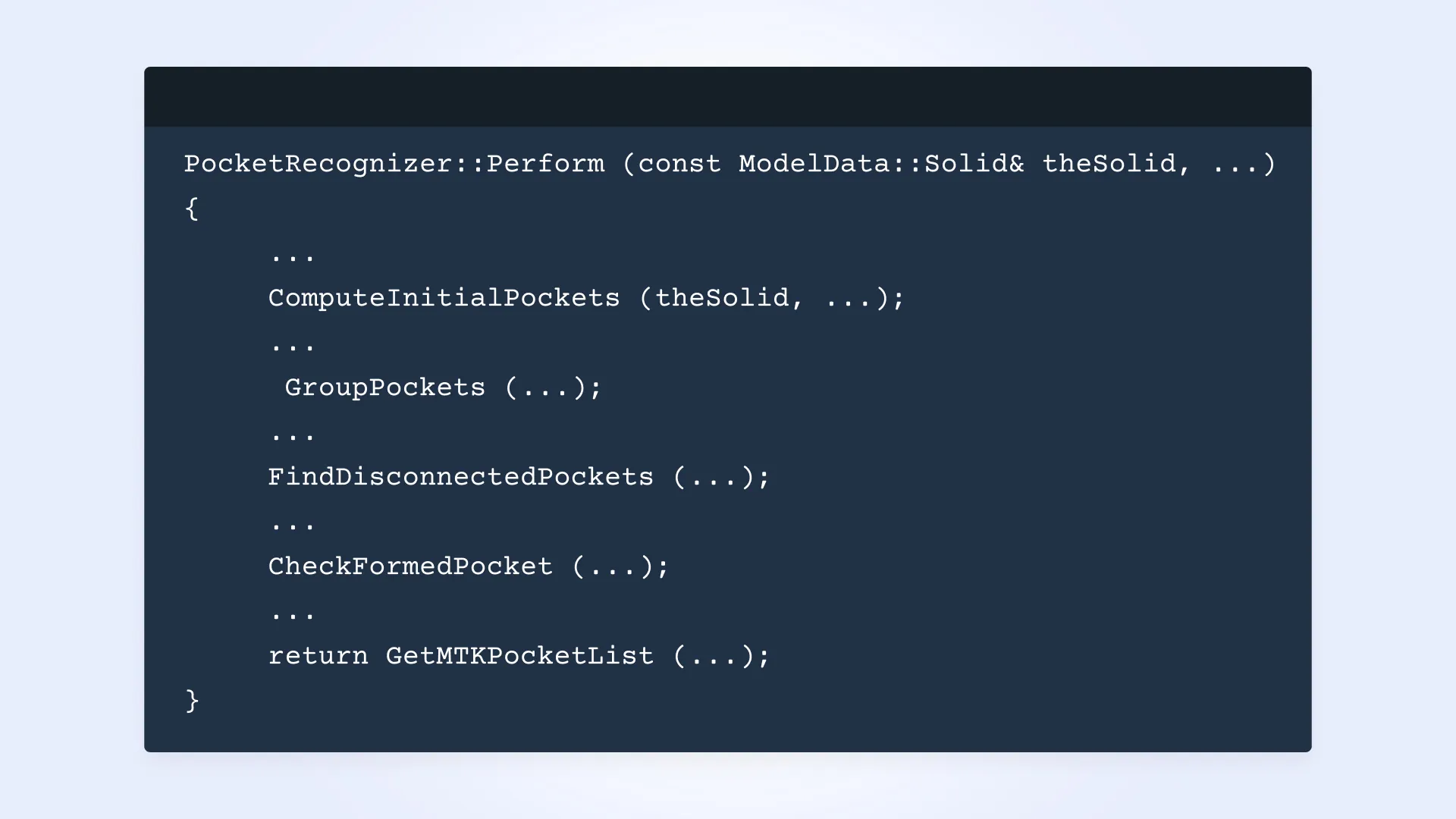
Of course, the logic is implemented in each particular phase (sometimes sub-…-phases) but even this simple code excerpt may help feel that there is high complexity in the code that deals with geometry and B-Rep topology.
Our approach: heuristics, not magic
We don’t use machine learning (yet). MTK was designed from the ground up to work with real-world neutral CAD models. What powers MTK’s feature recognition today is a mix of:
- Heuristic-based No reliance on design history or semantic metadata. Just geometry.
- Built for manufacturability We don’t just label features — we interpret them in the context of CNC, sheet metal, or molding.
- Smart geometry recovery If a shape looks like a cylinder or a cone, we check — and reconstruct it as one.
- Supports full workflow Feature recognition can be self-contained or as foundation for DFM checks.
More on that in future posts.
Final thoughts
Feature recognition isn’t magic. It’s a tough, ambiguous problem — and it gets harder as models get more complex. We don’t promise perfection, but we’ve spent years engineering something developers can rely on. Not a research paper — but a toolkit that works with real models, real tolerances, and real ambiguity.
If you’re building a cloud platform, a quoting engine, or a digital manufacturing solution — we’ve already solved this problem, so you don’t have to.
Try it in the browser or talk to us
Feature recognition is just one part of MTK. You can see it in action in our interactive online demos, where you can view features, DFM violations, and topology structure directly from a STEP file — right in the browser.
Have questions or want to integrate MTK into your own application? Contact us — or even write me directly. I’m the founder and product owner of MTK and would be glad to hear from you.