Manufacturing Toolkit overview
Learn what Manufacturing Toolkit is and how it empowers you to create cutting-edge software for digital manufacturing.

Introduction
The active development of digital manufacturing is impossible without software solutions that analyze 3D models from a manufacturing perspective. The results of this analysis provide knowledge about the technological processes and types of processing required to produce a specific model. Companies gain insights into how to design it more efficiently and cost-effectively, or at the very least, ensure that the model is ready-to-go for production.
To obtain this specific information, the software must support two basic functions – machining feature recognition and design for manufacturing (DFM) analysis. Developing such solutions from scratch is labor-intensive. To help companies focus on innovation and improving their products, CADEXSOFT provides the Manufacturing Toolkit, an all-in-one SDK to create digital manufacturing solutions.
What is Manufacturing Toolkit?
Manufacturing Toolkit is an all-in-one SDK designed to help developers create advanced software solutions for digital manufacturing.
Area of application
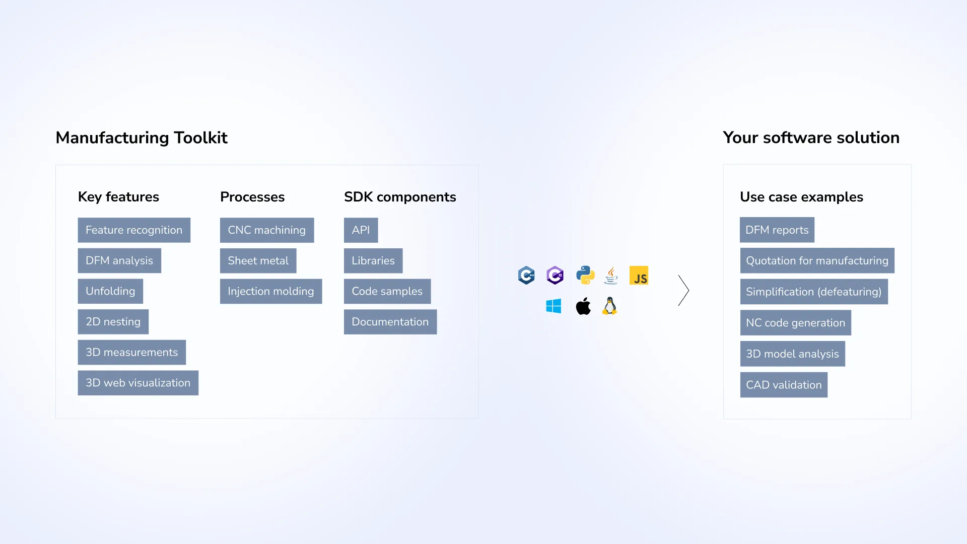
It can be used anywhere where machining feature recognition and DFM analysis are required. There are just a few examples of such solutions:
- DFM reports;
- Quotation for manufacturing;
- Simplification (defeaturing);
- NC code generation;
- 3D models analysis;
- CAD validation.
Benefits
The key advantage of the Manufacturing Toolkit lies in its versatility, providing a solution that works independently of specific CAD systems. When the STEP file is read, its content is converted into a neutral format, ensuring consistency across design and manufacturing workflows. The tool supports major manufacturing processes, including CNC machining, sheet metal processing, and molding.
Manufacturing Toolkit integrates easily into desktop, web, or on-premise environments. It provides libraries, APIs, code samples while supporting multiple programming languages and platforms such as Windows, macOS, and Linux. Additionally, it includes a TypeScript library to explore and visualize 3D CAD models on the web.
We have created a set of complementary features for the convenient extraction and analysis of process-specific information, and are continually improving it.
Manufacturing Toolkit enables your software to:
- recognize machining features;
- analyze Design for Manufacturing (DFM) and provide end-users with recommendations;
- unfold a sheet metal part to get an original flat metal sheet;
- perform 3D measurements, using advanced algorithms such as wall thickness;
- apply 2D nesting on flat materials;
- analyze 3D models.
How Manufacturing Toolkit works in your application
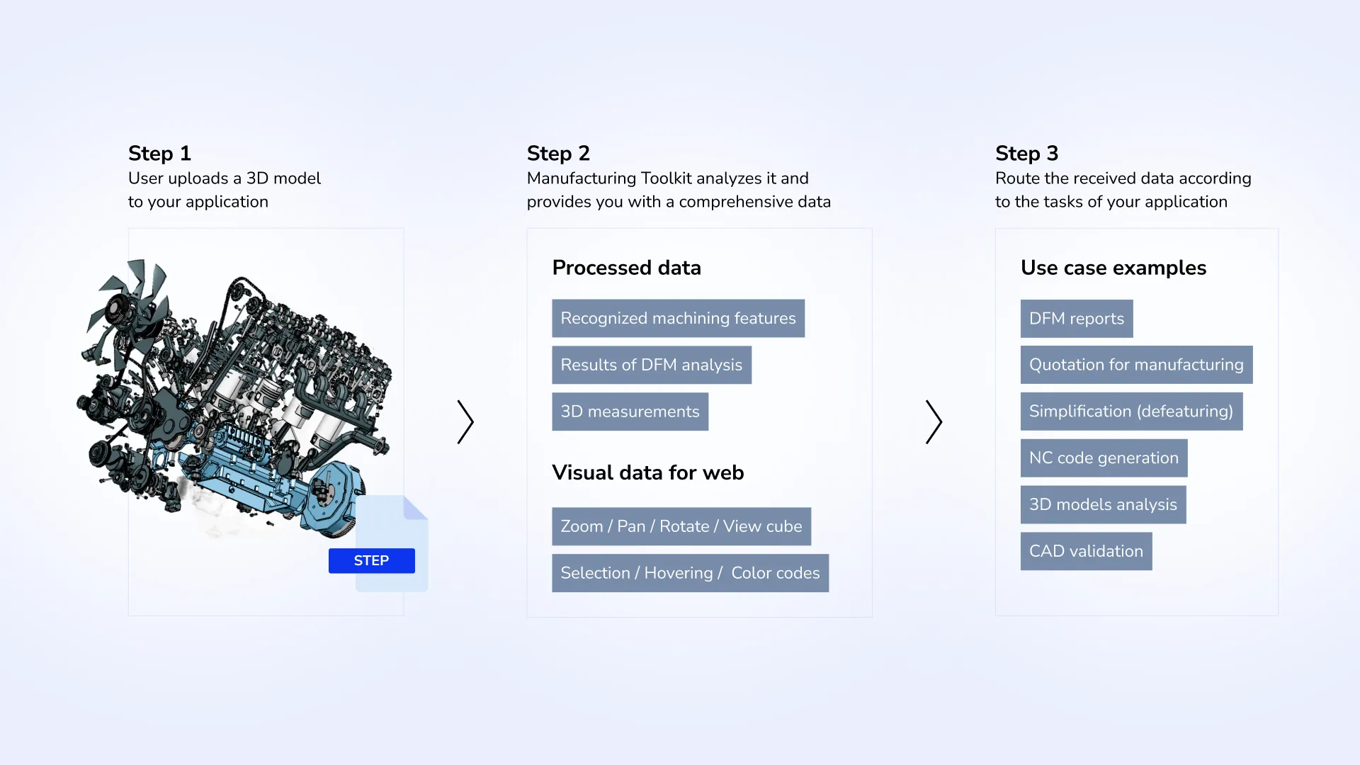
When a user uploads a 3D model, it is instantly analyzed by Manufacturing Toolkit. Its analysis generates a comprehensive data set that includes recognized machining features, DFM analysis results and recommendations, and a number of measurements such as surface area, cenroid, bounding box, volume, and wall thickness.
If you provide end-users with a web solution, they can interact with visual data via zooming, panning, and rotating the model with the intuitive view cube and color indicators.
Finally, the processed data is routed to meet specific application tasks, including generating quotations for manufacturing, creating NC code, conducting 3D model analysis, validating CAD designs, etc.
Supported processes
Manufacturing Toolkit covers major manufacturing processes: CNC machining, sheet metal processing, and molding.
CNC Machining
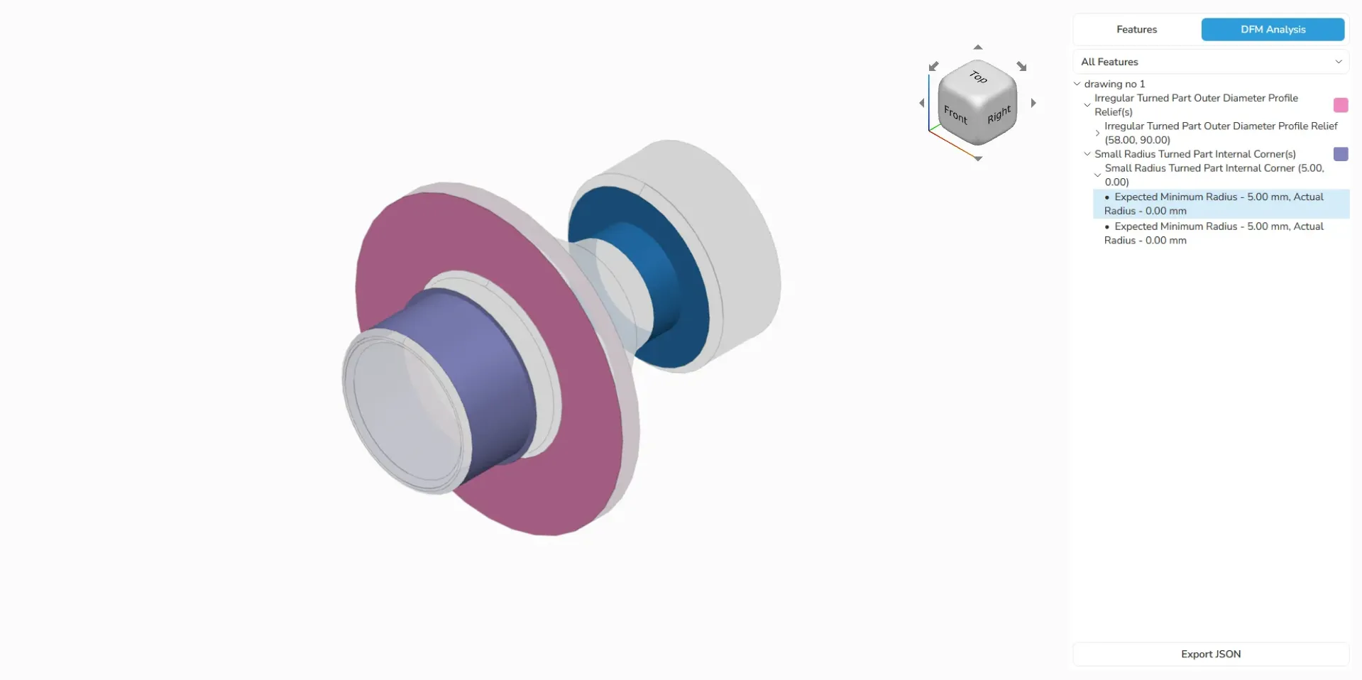
CNC machining uses computerized tools to precisely remove material from a workpiece, enabling the creation of intricate and accurate parts. You can recognize machining features, such as milling, drilling, and turning, and analyze them for possible design issues. You can use the obtained data, for example, in a virtual NC manufacturing simulation to prepare a 3D model for NC code generation.
Sheet metal fabrication
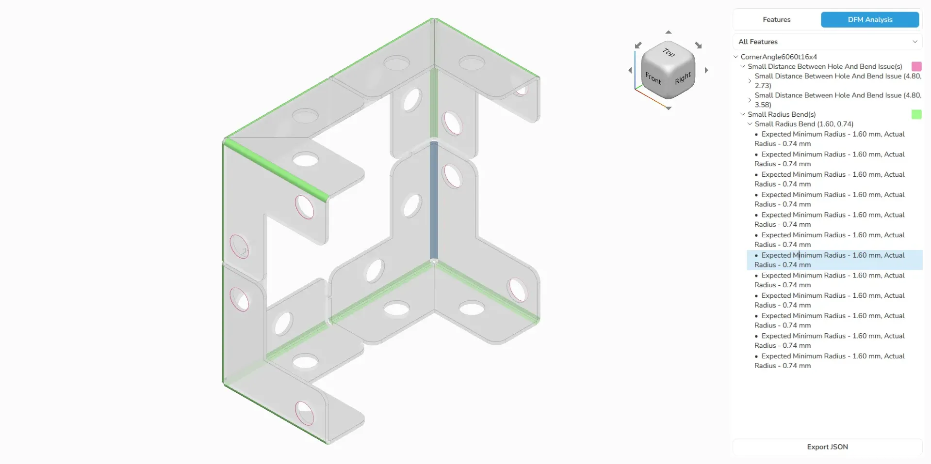
With Manufacturing Toolkit, you can streamline sheet metal processes by recognizing key design features, identifying potential issues, and generating flat patterns from 3D models.
Molding
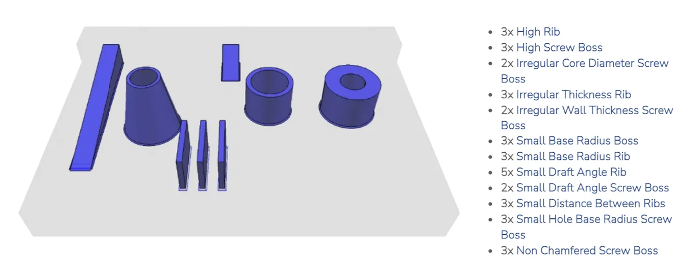
Molding shapes materials, often polymers, into specific forms using a mold. This process is used to produce complex, precise parts by pouring liquid material into a pre-designed mold. Manufacturing Toolkit offers tools to identify specific features, for example, you can recognize parting lines and draft angles and analyze them for potential design flaws.
Key features
Machining feature recognition
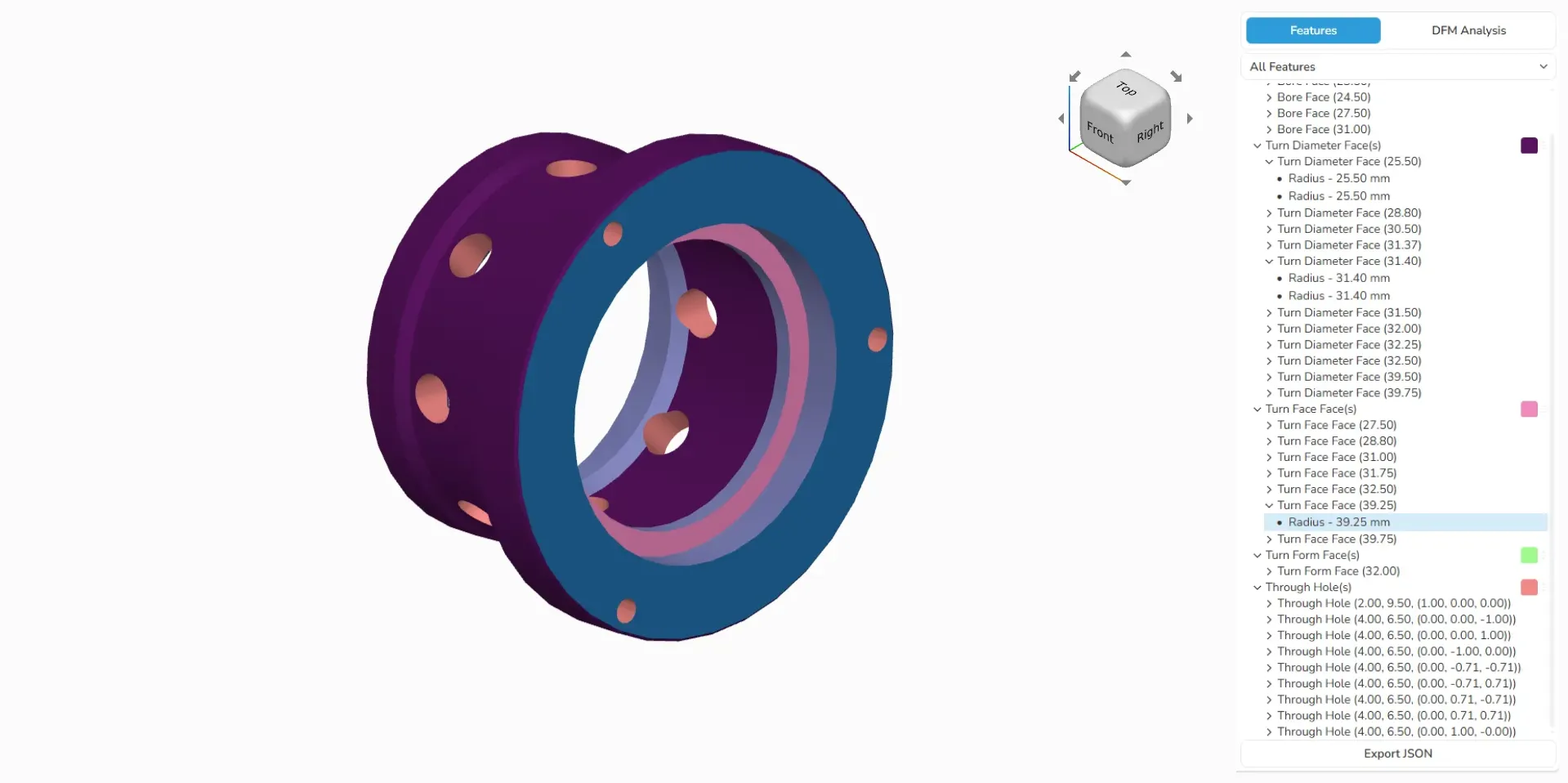
The ability to automatically identify and group topological entities is one of the key features of Manufacturing Toolkit. It allows you to streamline the design-to-production transition, reduce the need for manual intervention, and expedite the entire process. So you can be guaranteed that each component meets design specifications.
Examples of what you can recognize:
- CNC machining. Bosses, pockets, different types of holes, countersinks, and faces.
- Sheet metal. Bends of various types (simple, curved, hem or compound), beads, bridges, louvers, cutouts, holes, tabs, and notches.
- Molding. Ribs, bosses, and screw bosses.
DFM analysis
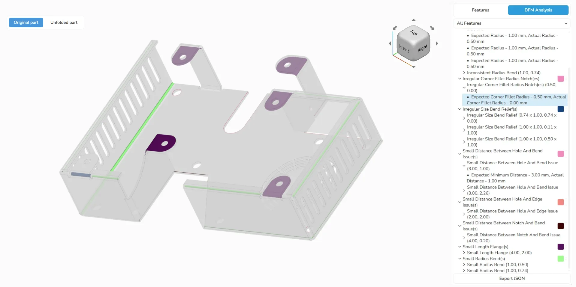
A DFM analysis allows your software to identify potential challenges and issues early in the design phase:
- CNC machining. Over 25 design flaws for machined parts from solid models, manufactured in subprocesses such as milling, drilling, and turning.
- Sheet metal. Almost 30 DFM checks, such as the small distance between holes, inconsistent bend radii, etc., from the shell and solid models.
- Molding. 15+ structural defects and potential production issues, for example, small rib and bosses draft angles from solid models.
As a result, you get precision in visualizing even small manufacturing details and receive a report with a list of errors to eliminate.
Sheet metal unfolding
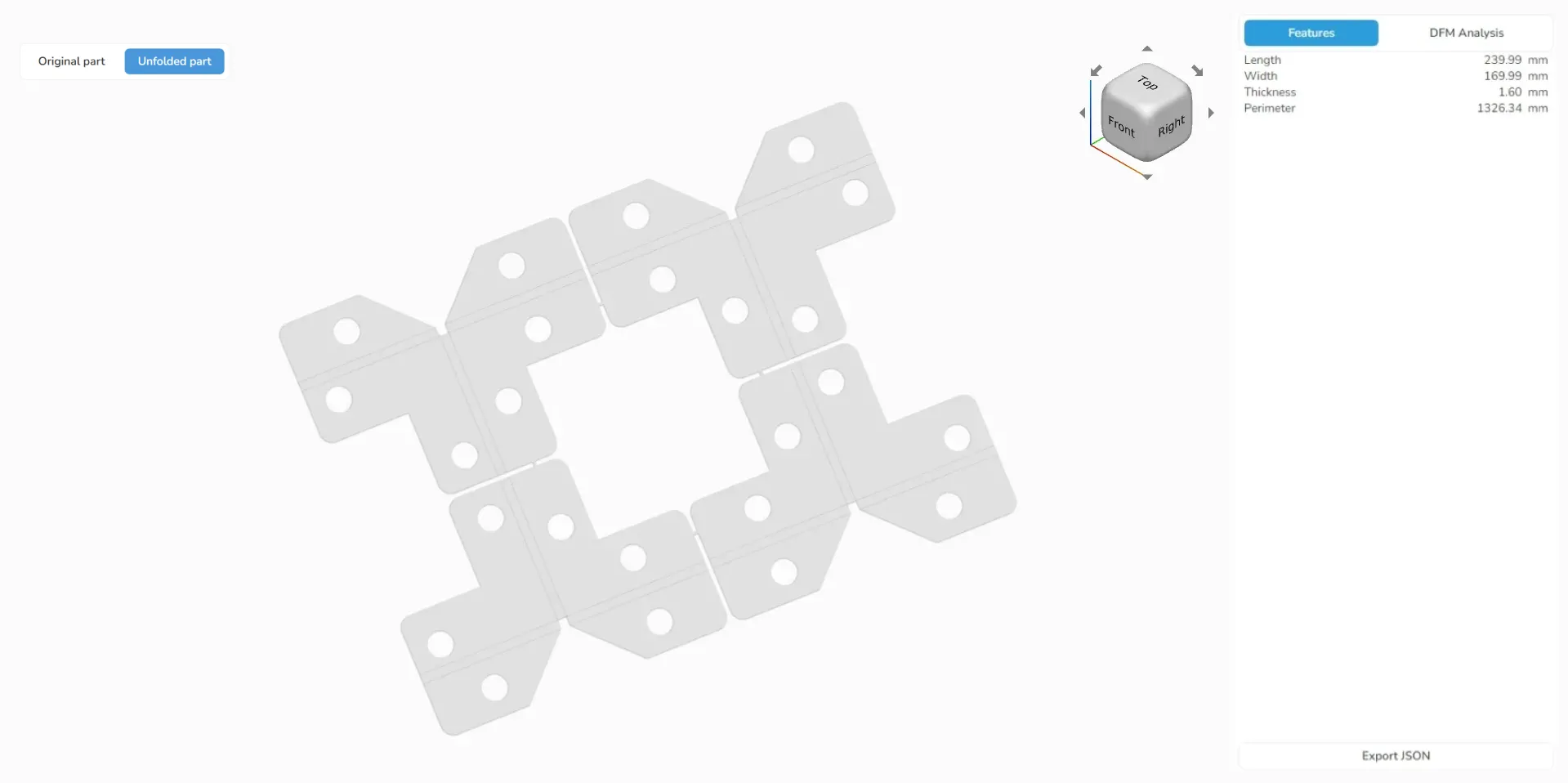
Manufacturing Toolkit generates an unfolded shell that represents the flat metal sheet that is fully compliant with the original 3D model. You can apply the algorithm to any piece, from simple to advanced with free-form surfaces. It is useful for various purposes, such as nesting, improving accuracy, and transferring results to CAD systems.
3D measurements
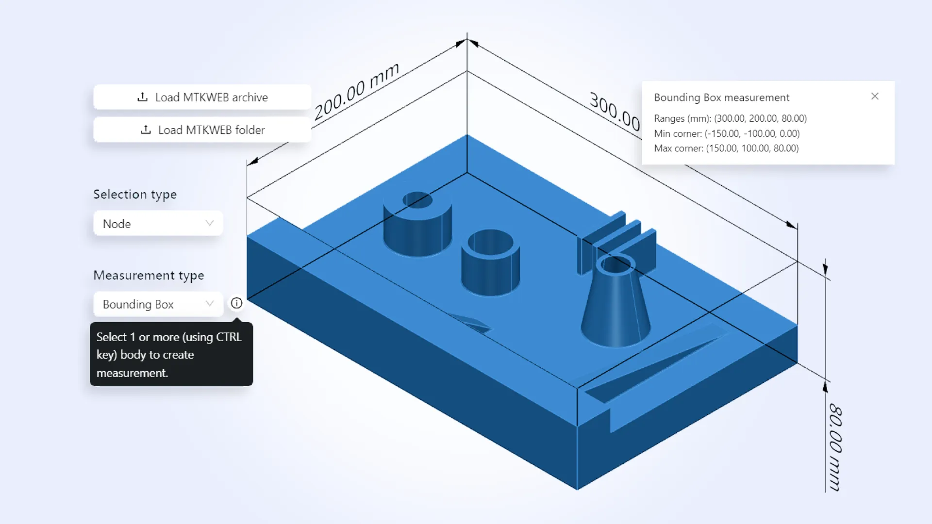
MTK enables your software to compute key properties for an entire 3D model or any assembly, instance, part, or part representation. You can get the following information: bounding box, surface area, volume, centroid (center of mass), and wall thickness.
Nesting
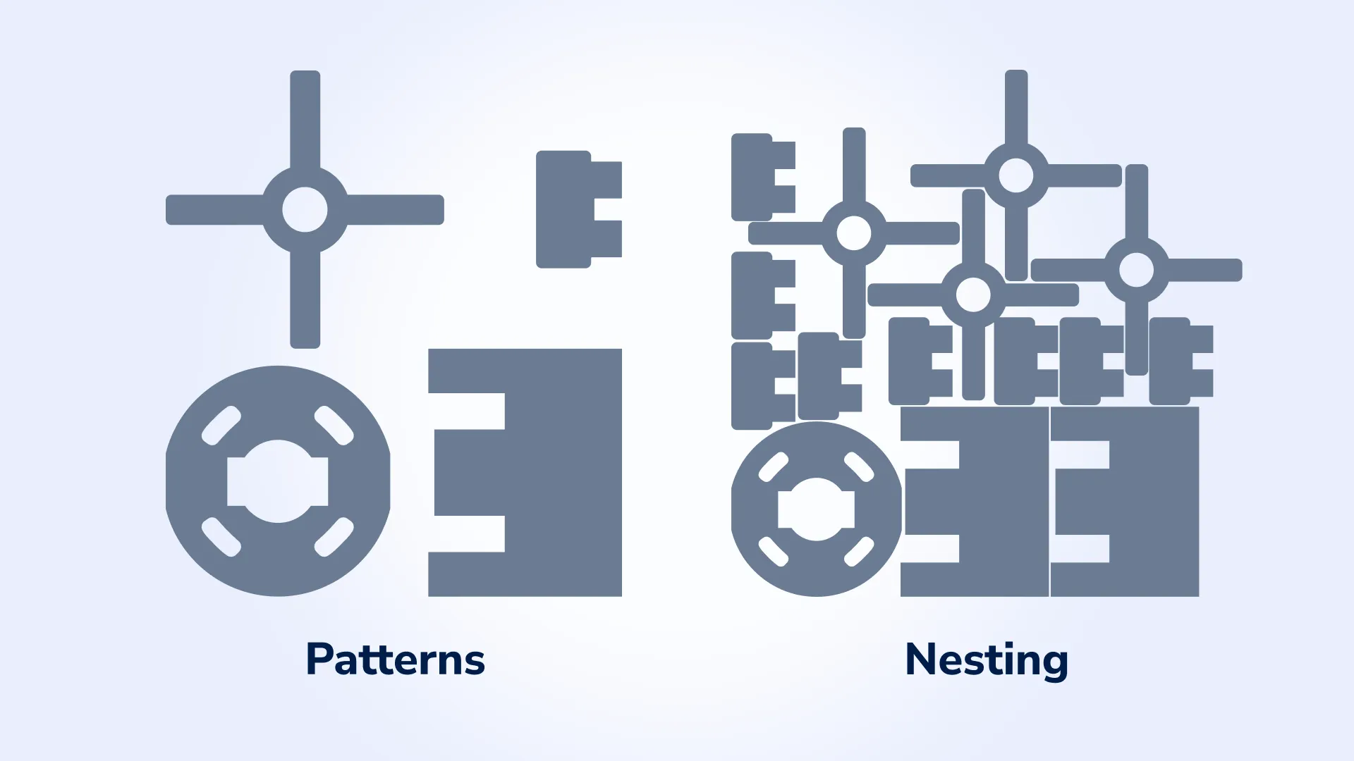
Nesting functionality enables your software to optimize the placement of multiple freeform 2D shapes on a sheet. The process starts with calculating layouts based on specified parameters and material properties. Once they are defined, our algorithm generates an optimal arrangement of patterns across the materials, minimizing material usage and maximizing space.
What are the components of the Manufacturing Toolkit?
The Manufacturing Toolkit is an SDK composed of several components designed to simplify integration and accelerate development:
API
The Manufacturing Toolkit API provides a comprehensive set of functionalities for analyzing and manipulating 3D models. With a common data model and a neutral .mtk file format, API also includes organized namespaces.
Data access
Using API, you can retrieve and manipulate the different types of data from the model:
- Geometric entities: access surfaces, curves, etc. using Geom:: namespace.
- Topological entities: interact with assemblies, parts, edges, and more using ModelData:: namespace.
- Measurements: obtain properties like bounding boxes, surface areas, and volumes using Measurements:: namespace.
- Drawing elements: work with drawing-related objects in the Drawing:: namespace.
Example usage
Here are some examples of how to use API:


Libraries
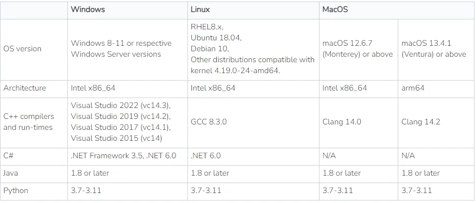
Manufacturing Toolkit’s libraries are precompiled and optimized for different platforms and programming languages, giving you the flexibility to deploy solutions in diverse environments.
- C++: Includes platform-specific libraries with versions for release and debug modes. Automatic linking simplifies the setup for Windows users.
- C#: .NET assemblies offer a .NET Framework 3.5+ compatibility for Windows-based development.
- Java: Lightweight libraries link with C++ libraries for powerful hybrid solutions.
- Python: Installable via pip, supporting seamless integration with Python applications.
- JavaScript: The Manufacturing Toolkit Web library is tailored for modern web applications, using WebGL for rendering.
Documentation
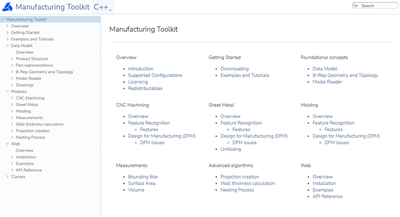
Manufacturing Toolkit offers comprehensive documentation to support you in integrating its features effectively into your application. The documentation includes detailed descriptions of APIs, classes, and methods, along with examples to demonstrate their practical use.
The documentation is structured into sections, has a search function, and is constantly updated.
Code samples
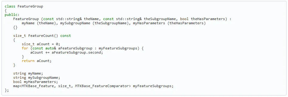
Manufacturing Toolkit includes samples to help you quickly explore the API and libraries. These examples demonstrate core functionality, such as analyzing 3D models, performing measurements, and integrating Manufacturing Toolkit into other software.
Web visualization capabilities
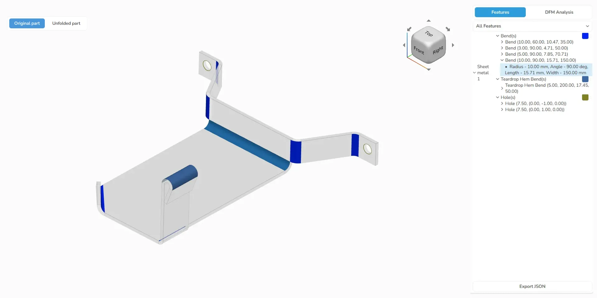
Our web visualization is based on the TypeScript library, assisting your users in exploring and visualizing 3D CAD models on the web.
Key features include:
- reading MTKWEB (our proprietary format, optimized for web usage);
- accessing product structures of assemblies and parts;
- supporting B-Rep geometry;
- providing data for visualizing 3D models.
Paired with Manufacturing Toolkit, it allows you to develop web applications running publicly or on-premise. Take a look at our web demo, you can a create similar visualization or integrate our ready-made UI right into your software.
Summary
The Manufacturing Toolkit is designed to provide fast and convenient access to process-specific information required in digital manufacturing solutions.
CADEXSOFT’s extensive expertise and know-how, paired with comprehensive documentation, regular updates, and responsive customer support, make the Manufacturing Toolkit an ideal solution for long-term projects, critical tasks, and sophisticated applications.
Experience the Manufacturing Toolkit with a free trial — click here to get started.